 Oppenheimer Precision Products Inc. (Horsham, PA) makes illuminated cockpit displays for aircraft, ships, and ground vehicles. “If it flies, swims, or crawls, we have panels for it,” is the company’s slogan.
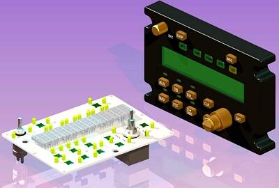
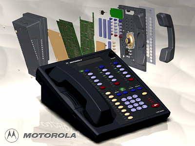
In the past, mechanical engineers at Oppenheimer used 2D CAD to document the layout of the acrylic panel that comprises the front portion of a cockpit display. (Behind these panels are printed circuit boards containing the lamps and electronics of the displays.) Originally, the acrylic panels were fairly simple parts with holes and cutouts. Over the years, however, as the complexity of the company’s products increased, it became harder to design them in 2D. Displays had to fit more functions into smaller areas, for example, and had to incorporate features such as push buttons and switches as well as light blocks to prevent the light of one lamp from illuminating areas governed by other lamps.
Designing these more complex products in 2D was a challenge because it was very difficult to detect interferences by looking at drawings. Also, without being able to see the volume they had to work with, engineers had trouble packaging the displays and making everything fit. For these reasons, the company began considering solid modeling.
They evaluated two programs: Autodesk Mechanical Desktop and Solid Edge from Unigraphics Solutions (St. Louis, MO). After experimenting with both programs over the course of a few weeks, they chose Solid Edge because it was much easier to use. “All of us found it possible to model something within half an hour with Solid Edge,” says George Fesmire, a project engineer at Oppenheimer. “Mechanical Desktop was so complicated that we couldn’t do anything without some sort of training.”
Time Savings
Since switching to Solid Edge, Oppenheimer has seen the time needed to design and document a simple package (an acrylic panel without switches or light blocks) decrease from four days to two. The time savings come primarily in the production of drawings. “With our 2D program, we drew every view from scratch,” Fesmire explains. “With Solid Edge, we draw a part once and make as many views we want.”
In addition, some of the time-consuming aspects of creating drawings, which were previously done manually, are now automated with Solid Edge. For example, for the convenience of the inspection department, Oppenheimer includes hole tables on drawings to show the precise location of each hole in a panel. In the past, someone had to determine the x, y location of all the holes, write down the values, and then type them onto the drawing. This was a slow process and also prone to error. Solid Edge creates hole tables automatically. It labels each hole and lists its x, y coordinates. “This is a big time saver, and it also ensures that the locations are accurate,” Fesmire says.
While drawings are used primarily by inspectors, machining the panels is done directly from the Solid Edge geometry. Manufacturing engineers import the CAD data into the Mastercam CNC programming system from CNC Software Inc. (Tolland, CT). As a Solid Edge Voyager member application, Mastercam provides an additional level of integration with the design geometry. Working from Solid Edge data rather than drawings reduces the time to create toolpaths by up to several days, depending on the complexity of the panel.
Complex Project
Although these time savings are important, Oppenheimer finds that the use of Solid Edge brings additional, less-quantitative benefits to more complex projects. “The main reason we use Solid Edge on the really complex projects is to be able to see what we can’t see in 2D,” says Fesmire.
A good example is an experimental GPS panel that Oppenheimer recently developed for the Navy and a major prime aircraft contractor. As a cost-cutting measure, the clients wanted to use a commercial GPS product as the basis for a new instrument in helicopters. The panel that Oppenheimer was asked to design required many buttons and enunciators, and because the envelope was so small, the components had to be placed very close together. The packaging was so tight that it was even necessary to find a new method for creating light blocks. Normally a designer embeds black slugs into the acrylic and machines out holes to create individually lighted areas. In this situation, the slugs would have been machined so thinly that light would shine through them anyway.
This project was originally started in the 2D CAD system. It was transferred to Solid Edge when it became impossible to make everything fit properly while working in only two dimensions. “I couldn’t see what was going on,” says Fesmire, who worked on this design.
After modeling the individual components as solid objects in Solid Edge, Fesmire was able to assemble them on the screen to find the best configuration. “The nice thing about working with Solid Edge is that I use more design skills than drawing skills,” says Fesmire. “When you’re used to drawing everything precisely from the start [with 2D CAD], it’s a new way of thinking. But once you’re comfortable with it, this is a much better way to work.”
For the light blocks Fesmire ended up embedding almost paper-thin pieces of aluminum into the display. By modeling the device in solids, Fesmire was able to see how to best fit all the components together. He was also able to use the superior visualization capabilities afforded by solid modeling to find interferences.
These features, combined with the fact that drawing time was cut it half, enabled Oppenheimer to reduce total design time for this project by 20 percent compared to working in 2D. “But the real benefit,” Fesmire says, “was that we could see well enough what was going on inside that small package to be able to improve the design.”
Design complexity drove Oppenheimer to solid modeling. Now that the company has Solid Edge, it has confidence that its design environment can keep pace with future developments in cockpit display technology.
Oppenheimer Precision Products, Inc.


