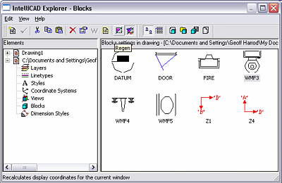
Its most common use is for selecting layers to display or not, and setting their colours, linetypes etc. ‘Styles’ refers to Text Styles. Coordinate systems (UCSsettings) are for 3D operation. Dimension Styles is valuable for organising dimensioning settings and copying pre-done setttings from previous drawings. Here, we are only concerned with its Blocks feature. Note that this includes XREFs, if any. They get shown as Blocks in iExplorer, but are identified as XREFs and their source folder path identified, in the Properties right-click panel.
In the above illustration, iExplorer is open at the Blocks display and the current drawing does in fact have some Blocks, as you can see. This is the View, Images option. The View, Details option shows the Block names, the number of times that block is at present inserted into the drawing, the coordinates of its internal reference point, and whether it is actually an Xref attachment. The Images display option will normally be the more useful.
You can see that there are two drawings currently open in IntelliCAD because there are two main entries in the left pane, one of which has yet to be named and saved, as it is shown as ‘Drawing1’. One of the most powerful features of iExplorer is that it allows you to select component items from another open drawing and copy them into your working drawing. This can save a lot of time specifiying complex dimension styles for example.

IntelliCAD Block Explorer
In the case of the Blocks section, it allows you to copy Blocks out of other drawings. It also provides a convenient means of saving blocks to separate external files, instead of using the typed WBLOCK command. In its Images view, it also gives you a visual overview of all available blocks, or as many as will fit in the display at once, rather than the one-by-one preview in the Insert Block dialog.
Not all the available commands are on the drop down menus – only those that apply to iExplorer generally. The vital commands for Blocks are found on the right-hand Toolbar section that changes for each component display option. For the Blocks components, the toolbar buttons are, left to right from the toolbar divider:
- View as Images
- View as Details
- Insert Block
- Insert External File Blocks
- Save Block
- Attach Drawing
Buttons 1 & 2, view options – have been explained above.

Using buttons in the block explorer
Button 3, Insert Block -makes the iExplorer display vanish temporarily and the command-line based INSERT command runs for the selected block. This prompts for insertion point, X scale, Y scale, and rotation angle. Then the block is inserted and immediately the iExplorer reappears over the drawing, ready to do another insertion or be closed. If you double-click on a block name, it is the same as clicking button 3.
Button 3 also has a slightly different function, and this is where it facilitates the use of a symbol library created as a blank drawing containing a lot of blocks – a single-file symbol library. This usage is detailed below.
Note that it appears as if you can select a block from another open drawing and insert it directly into the work drawing. But it is not so. It goes through all the prompts but nothing happens in the end. See the use of Single-file Libraries below for how to actually achieve this.
Button 4, Insert External File Blocks– pops up an Open File dialog box the same as clicking the Browse button on the Insert Blocks Dialog.
Button 5, Save Block– does the same as the typed command WBLOCK. It saves the selected block to a separate DWG file, and pops up the Save File dialog for you to specify where and what file name.
Button 6, Attach Drawing– ‘Attaches’ a DWG file as an XREF. The subject of XREFs is too complex to deal with here, and is irrelevant to the topic of Symbols. Using iExplorer with single-file Symbol Libraries
If you are creating a drawing and want to use a symbol library contained in a single drawing file, the procedure is as follows. It may appear that a different procedure is also possible, but the following is actually the only way that works to my knowledge.
- You have the drawing open that you are working on – let’s say Drawing1.dwg
- Open the Symbols Library drawing also – let’s say it’s called Symbols.dwg
- Use the Window menu to select the Cascaded display option, and make Drawing1 the active drawing, by clicking its header bar.
- Pop up iExplorer by the Settings, Explore Blocks menu. It will show the blocks in Drawing1, if any exist yet.
- Click on Symbols.dwg and expand it to show its blocks, preferably in the Images view option.
- Click on the wanted symbol block so that it highlights as selected.
- Click on the Insert Block toolbar button. The display changes to show the blocks in Drawing1, with the selected block added.
You can repeat the above if you want to copy several symbols that you know you will be using, or you could have selected more than one in step 6 by the usual Windows method of clicking additional ones with the Ctrl key held down, or clicking first and last with Shift held down, so that several are highlighted. This will usually be the best strategy.
Up to this stage, you have the wanted blocks copied into the invisible Blocks definition area of Drawing1. Now you need to insert them.
You can insert them while iExplorer is still active, by selecting one block in the Blocks section of Drawing1, and clicking the Insert Block button, or by double-clciking a block image.
Alternatively you can dismiss iExplorer, and use the Insert, Block menu to insert the blocks as desired. This method pops up the Insert Block dialog where you select the block by name from the drop-down list and check it in the preview, and have the option of presetting its insertion scales to 1.0 (or whatever is appropriate) to avoid the two prompts for scale when inserting. This way is more convenient if you want to insert symbols in between drawing lines and text, etc.
* I think this scheme of using a single-file symbol library and iExplorer is by far the best way of managing symbol libraries. I described how to create a one-file symbol library in the previous training note.
Ready-made Libraries
Instead of creating your own library, you can alternatively buy ready-made symbol libraries that are intended for AutoCAD but also work equally well in IntelliCAD. Most such libraries are provided in the form of a large number of small individual Dwg files collected into a folder, as was needed for AutoCAD prior to 2000. Some now also provide the same symbols collected into single-file libraries intended for use with the AutoCAD Design Center in AutoCAD 2000 and later. These single-file libraries are ideal for use with IntelliCAD Explorer.
One source is Autodesk – ‘Autodesk Symbols 2000 International’. These are sold in two bundles. One box is a collection for engineering use and the other for architectural use. You get over 12,000 symbols, and they are duplicated in individual dwg files and one-file collections. There are also separate sets for the national standards of USA/Canada, ISO-metric (for Australia, NZ, and many other countries), British metric, German DIN, and Japan. You do get a lot of trivial and rather useless symbols, but also all the needed ones, and all correctly drawn to the standards. Autodesk had each set created in the appropriate country. Selling libraries on CD neccesitates bundling a lot together, so that the price can cover the distribution and stocking overheads once only rather than incurring the same costs for each of many small sets. Those costs are more than the cost of supplying the data! These Autodesk libraries are a cost-effective solution for many firms, compared to paying their own staff to reinvent the wheel.
Alternatively, search the internet, but beware of badly created symbols, especially free ones. Most are for USA standards which are useless anywhere else, and Asian sources tend to be rather variable in symbol design, as they have scant regard for any standards. The Autodesk Symbols are available from on-line shops and directly from developer websites.


