
Line weights, or the varying line thicknesses used in engineering drawing, are essential in creating a drawing that communicates efficiently.
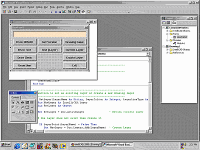
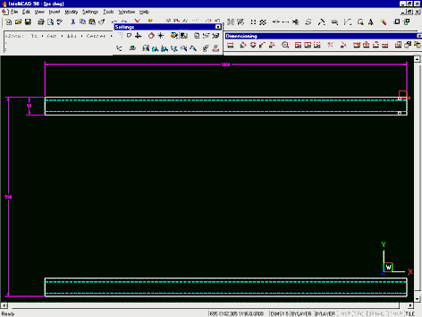
While line weight is an important factor on drawings, it is only so on hardcopy documents. Different line thicknesses on screen are of no value and, if you were to use them, would be a hindrance. Instead, different line types are shown in colours which can symbolise a number of attributes of the line work. The CAD user soon subconsciously equates line colour with plotted line weight and simultaneously any other attributes the colour may represent in his or her office standard. Our focus in this article set is on the relationship of colour in a CAD drawing to line weight when that drawing is output on paper.
An engineering drawing is a highly stylized graphic representation of an idea. The idea might be of something that we can see such a real or virtual object, space or environment. In some cases, such as an electronic schematic diagram, for example, the drawing will bear no visual resemblance to the physical object that will be built from the information it provides.
In every case with the possible exception of “3D” and rendered drawings, which communicate with a different graphics language, we can understand engineering drawings only because we can understand the basic language of technical graphics.
Line weights are a vital part of conventional technical graphics language. They are embodied to the extent of being defined in national and international standards.
Line types and line weights allow drawings to communicate information that would otherwise be very difficult to convey. For example:
- Hidden outlines
- Paths of motion
- Planes of symmetry
- Fictitious outlines such as major and minor diameters of screw threads
- Dimensions and projections
- Materials (hatching)
- Centres and imaginary intersections
Conventional practice is that only two different line weights be used on any one drawing. This is subject to discretion, and some disciplines regularly use three, and occasionally four, different line weights. Consistency and clarity of communication are the deciding factors. You could use 10 line weights in a drawing provided everyone understood what they all meant, and the document was consistent.
The thinnest line should be no less that 0.18mm. Finer lines are difficult to read and impossible to reproduce easily.
Line weight groups chosen for most engineering drawings are selected from adjacent pen thicknesses (in mm). The table below indicates line weight groups for various sheet sizes. Pen thickness is shown in mm.
| 0.18 | A4, A2, A3 | ||
| 0.25 | A1 | ||
| 0.35 | A0 | ||
| 0.50 | |||
| 0.70 | |||
| 1.00 | |||
| 1.40 | |||
| 2.00 |
Typical Applications
Engineering drawings made on A4, A3 and A2-sized pages are at the smallest end of the range of document sizes that would reasonably be used. As such they would use a pen rage at the documents might use a pen group from the fine end of the scale. 0.18, 0.25 and 0.35mm pen widths.
Line type |
Thickness |
Example |
Application |
|
Fine |
Thick |
|||
| Continuous thick | 0.35 | 0.50 | Visible outlines, existing features, cut edges, general line work | |
| Continuous medium | 0.25 | 0.35 | Used where another level of line weight would assist the delineation e.g. internal line work, notes | |
| Continuous thin | 0.18 | 0.25 | Fictitious outlines, imaginary intersections and projections, hatching, dimensions, break lines | |
| Dashed thick | 0.35 | 0.50 | Hidden outlines and edges | |
| Dashed thin | 0.18 | 0.25 | ||
| Chain thick | 0.35 | 0.50 | Indication of special surface requirements or (sometimes with a text component) to indicate pipelines and services | |
| Chain thin | 0.18 | 0.25 | Centre lines, motion paths, indication of repeated detail | |


