I like tools. All kinds of tools. As a matter of fact, I have a garage full of them. I also believe that it’s a mistake to turn every problem into a nail just because the only tool available is a hammer.
I carry the same philosophy into my professional work as a CAD detailer. I manage to pound out the majority of this work using plain ol’ AutoCAD … but there are times when pounding just doesn’t get it. So I need another tool. Rhinoceros (Rhino) is an excellent case in point.
With the enhanced solids modeling capabilities of AutoCAD (R14 & 2000), I’ve simply adopted the practice of full-fledged solid modeling of the concrete structures I detail for my clients. Several projects have come my way recently that included things like spiral garage ramps. Granted, these can be approximated using surface patches and such, but my clients need a more accurate picture with extractable data points along any edge or on any surface at any location. That’s where Rhino has been a tremendous asset in my toolbox.
I’m a novice RHINO user to be sure, but I have found that the ease with which I am able to create the necessary elements for detailing models and the simplicity of getting them into AutoCAD testify to the ease-of-use aspect of the program.
Rhino comes on CD like just about everything else nowadays. It also comes with printed documentation – in color! The manual shows attention to detail. Several well-illustrated tutorials with prepared material on the CD will help just about anyone get up to speed quickly.
The installation process is a “no-brainer.” Just stick the CD into the drive, interact with a few dialogs and you’re done. A very nice feature is a “Web Install” function for upgrades. This allows upgrading directly from the McNeel server.
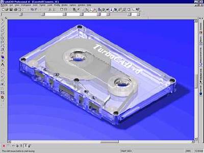
The default Rhino editor layout contains four viewports configured as the top, front and right side views, and a perspective view. As with all aspects of the interface you can customize the layout to your preference. Each viewport can also be stretched to fill all or any portion of the screen.
 in Rhino.") Navigating in the Rhino viewports was a little confusing at first. Like most 3D modeling applications, object creation is done on construction planes. In AutoCAD this is represented by the XY plane of the User Coordinate System (UCS). Rhino is no exception. However, being accustomed to UCS behaviour in AutoCAD, it took me by surprise to find that the UCS could be different in one viewport from another. AutoCAD 2000 finally has that functionality.
Navigating in the Rhino viewports was a little confusing at first. Like most 3D modeling applications, object creation is done on construction planes. In AutoCAD this is represented by the XY plane of the User Coordinate System (UCS). Rhino is no exception. However, being accustomed to UCS behaviour in AutoCAD, it took me by surprise to find that the UCS could be different in one viewport from another. AutoCAD 2000 finally has that functionality.
Another interesting aspect of object creation in Rhino is the ability to complete commands in one viewport which were initiated in another. Not simply in the sense of specifying the other endpoint of a line, etc. The cursor is active in all viewports, simultaneously providing good 3D feedback while creating elements of the model.
The command set should be familiar to any experienced CAD user. Basic object primitives such as lines, arcs, circles and polylines use the same commands. The Tools > Options > Aliases dialog provides a means of customizing commands to single keystroke entries to further enhance the useability of the program.
An example of the sort of modeling tasks that Rhino makes simple while being virtually impossible in AutoCAD is a helical ramp. Rhino provides a number of methods for generating freeform shapes – in this instance a one-rail sweep works best for what I need to accomplish. This is roughly equivalent, but far more powerful than the AutoCAD extrude-along-path solid extrusion feature.
 The first step involves creating the helical path using the Rhino helix command. The Rhino command line (yes there is a command line!) Allows entering either relative or absolute coordinate data in direct response to command prompts. The coordinate system origin defaults to the center of each viewport. This is perhaps the place to mention the from the program: However, there is no support for imperial (feet/inch) units entry! The default measuring unit of inches makes it somewhat less cumbersome, but feet/inch entry would be much handier.
After creating the helix, a profile of the ramp is drawn relative to the path along which it will be swept. (see figure 2). In this example the ramp is defined by the inside radius (10’-0″, or 120’’in Rhino-speak) and the helix defines the top inside corner of the ramp section. The actual sweep operation, selected from the pulldown menubar or entered at the command line brings up the dialog shown below.
 Rhino allows control of how the resulting form is generated by selecting the desired “style” from the pulldown listbox. As with many of the commands and command options, Rhino uses somewhat colloquial terminology. Which in the larger context imparts a high degree of intuitive understanding to the interface.
In this instance, for example, we want our ramp to be generated in a “Roadlike” fashion as viewed from above; Roadlike-top from the pulldown. One additional step is required to produce a “solid” solid, and that is you have to “cap” the ends of the swept profile. Without these caps the sweep appears in AutoCAD as a hollow extrusion.
Rhino provides some dimensioning tools but makes no claim to being a full-featured application for documenting a model.
Models are exported in SAT format using the File > Saveas option. SAT is the native ACIS solids modeling file format used AutoCAD.
 SAT files are imported to AutoCAD using the ACISIN command. The Rhino export honors the coordinate system origin used to create the model.. Thus it comes into the AutoCAD editor window in proper relation to the current UCS. This should be taken into account during construction of the model in Rhino.
Illustrated is the ramp model as it appears in AutoCAD. To emphasize that the object is indeed a true 3D solid, I’ve drawn and extruded a circle and an arbitrary closed polyline at elevation 0, then extruded them to the height of the top of the ramp. In the image on the left both extrusions were unioned to the ramp to determine the intersections of these shapes to the surface of the ramp. At the right, both extrusions have been subtracted from the ramp. The result is clearly something that is all but impossible using ordinary AutoCAD without any add-on helpers.
Summary
I have only described one small project created in Rhino, but it serves to demonstrate the key factors of the program—ease-of use, speed of object creation and power.
You might consider Rhino as the Swiss army knife of 3D modelers. I personally think of the one and two rail sweeps used to create free-form objects as true solids in AutoCAD as the Big Blade. And when I need to model these kinds of objects, a hammer just doesn’t cut it.
UPDATE NOVEMBER 2009
Since Dennis Shinn wrote this reveiw some years back interest in Rhino has continued to grow and demand for this document is also very high. McNeel’s Rhinoceros software is now in release 4.0 and offers the following features…
- Uninhibited free-form 3-D modeling tools like those found only in products costing 20 to 50 times more. Model any shape you can imagine.
- Accuracy needed to design, prototype, engineer, analyze, and manufacture anything from an airplane to jewelry.
- Compatibility with all your other design, drafting, CAM, engineering, analysis, rendering, animation, and illustration software.
- Read and repair extremely challenging IGES files.
- Accessible. So easy to learn and use that you can focus on design and visualization without being distracted by the software.
- Fast, even on an ordinary laptop computer. No special hardware is needed.
- Affordable. Ordinary hardware. Short learning. Priced like other Windows software. No maintenance fees.
Over the years we have only ever heard complimentary remarks about Rhino and the McNeel organisation. The continued prosperity of both speaks for itself. Your comments are welcome.
![Ashampoo 3D CAD Professional 5 [Download]](https://www.cadinfo.net/wp/wp-content/uploads/2015/11/A1Aa31SjA-2BL.png)


