From the years of experience using CAD and all of the talk of late in trade media, the importance of standards is becoming ever more apparent to managers and business owners. The development of consistent standards and practices enables power and spawns exponential growth in production and capability.
Along with the development comes more capability and more data, but more standards to be managed. In order to manage, you must classify. Through classification, you break down complexity into manageable components. In CAD, classified components become objects that can be managed effectively. More and more characteristics (data) can be added to objects making them more manageable. Once manageable, they can be programmed to interact according to predictable rules of behaviour using intelligence like a brain does, and hence we have intelligent objects just like intelligent people.
The trick is to apply the right balance between power and flexibility, and leave open ways in which less predictable requirements can be addressed when they arise. Standards must also be dynamic and be allowed to continue evolving. They cannot become so entrenched that they stifle ingenuity and stop technological advances from being implemented. Standards must be changed over time and be maintained in step with technological advance, tempered for local requirements.
Technological Advances
In AutoCAD 2000, lineweight has been made another property tied directly to your drawing entities in the same manner as color and linetype. In addition, Plotstyles have been introduced, but I’ll talk more about that later.
Now, the added complexity of having linewidth always tied to color has been removed. Color can be used more freely and effectively to communicate much more information. I have long been a strong advocate in using colors, and CAD management systems such as S-MAN have always used color extensively for both visual and computer coding for objects, with appropriate linewidths attached. With the new lineweight property in AutoCAD 2000 you can now do this more easily, and it presents a major change in thinking about how your CAD system needs to run.
Consider that the purpose of linewidth is to provide contrast between components on paper in order to convey what the designer is intending to tell the person reading the print. Since no other person knows this better than the original designer, I recommend that the linewidth property always be used whenever a new entity is drawn. It will seldom need to be changed and in house productivity tools can be implemented to automate its use.
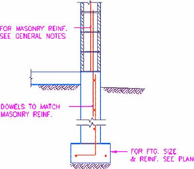
 While getting used to new software, the pressure to get things done to meet deadlines has caused the focus to be on using the tools to perform traditional drafting functions but do them faster. Consequently, classification of drawing elements was focused around drafting functions. For example, drawing elements were grouped on layers for center lines, hidden lines, hatching, linewidth, and text height. Outside of hatching where causing regens used to be a problem, it is remote that any of these elements need to be turned on or off individually. It is much more useful to classify the elements by the real life object and the object’s components. The following is an example for a typical detail drawing of a concrete footing with a masonry wall on top of it. The classification for detail drawings can be the object itself and its material components that are of interest to different trades.
Think real world objects! It’s a concrete footing for a masonry wall composed of concrete, masonry, and steel reinforcing. It is not 0.50 mm lines, 0.25 mm lines, 2.5 mm text, or dims. Such characteristics do not describe the object and are of no importance for classification.
It is a concrete footing with a concrete face, a concrete joint, earth or gravel in contact with it, text describing the concrete assembly, and it may have concrete dims delineating its size. It has other objects which are component objects contained in it or attached to it that define its makeup. These are masonry units with masonry grout lines, and reinforcing steel. It might also have anchor bolts made of steel. What is important is that it is composed of or associated with 3 or 4 different materials or sub-systems, some of which may already exist, and some which (in design work) are “Proposed” for modification.
To be able to identify the components instantly, the heavy concrete is blue (150), the masonry is blue-grey (152), the reinforcing steel is red (10), and the earth is burnt auburn (224). The thin concrete joint is blue-grey (153) and if wood plates were attached, they would be represented in the color range of #30-39 (yellow-orange).
Layers for grouping these objects can be Proposed Concrete (PCON), Proposed Masonry (PMAS), Proposed Reinforcing (PREI), and Earth (EART). The text annotation layers can be Proposed Concrete Text in various formats depending upon the standards you prefer (PCON_N, CONC-PT, or ANNO-TEXT-CONC-NEWW). The dims annotation layers can be also be PCON_N or be separated as CONC-PD, or ANNO-DIMS-CONC-NEWW.
With this type of classification, it is a simple matter to recognize components, and to display or not display various materials and their annotations. In the plan drawing, the same color coding is used but the layering is classified for the component objects rather than the materials. For existing works you would use ECON or CONC-EXIST for details, and E1WAL or WALL-CONC-EXIST for plans, going from generic to specific, depending upon how you use it. These are examples of the concepts.
The direction the industry is going for classifying detail blocks is to use the Uniform Construction Index, Divisions 1000 to 16000 for storing details in your block library. In this format, the detail above would be stored under a Div. 3 – Concrete folder in a 3100 – Cast in Place sub-folder, and the masonry components would be stored under another hierachy for Div. 4 – Masonry.
Plotstyles in AutoCAD 2000
Plotstyles are an extension of the object oriented approach in that they are a grouping of all of the plotting properties in one place. Where density (or screening), and various other plot settings were set in the software of the plotter driver in R14, these settings are now all in one place in a “Plotstyle Table” that is selected and attached to your drawing at plot time. The plotstyle table in AutoCAD 2000 is an enhanced replacement for the PCP files used in R14 and now links plotter driver settings for definition by color or by object names.
Plot settings can be defined according to the color code you use in “Color Dependent” plotstyle tables (*.CTB tables) or for objects directly by way of Named Objects in Named plotstyle tables (*.STB tables). The Named Plotstyles that you define in a Named Plotstyle (STB) table are the classification of plotting characteristics (properties) under the names of the objects for plans and of materials for details. In AutoCAD 2000, the name of the object or material (Plotstyle Name) can be applied to your drawing elements as another new property in addition to the new lineweight property. Hence all the plotting properties are classified under names of objects.
Note however that there are 2 kinds of drawings in AutoCAD 2000, “Color Dependent” and “Named”. You must determine which system your office wants to employ and stick to it. One system uses the color dependent plotstyle table and the other uses the “Named Plotstyle” approach where the plotstyle name links the drawing element to the plot file by way of the new plotstyle property. I recommend that you do either one of two things:
- develop a full object color coding system and use the Color Dependent system. When you migrate to the Named system, you will simply apply names to your color coding system and proceed to apply the plotstyle property to drawing elements. Utilities and systemized processes provided with the S-MAN Standards Managers by Softco will apply lineweights and named plotstyles to all of your drawing elements according to color in Named plotstyle drawings. You can choose old PCP or PC2 files for lineweight or map both of the new properties to color in user defined setup files.
- proceed to the “Named” system right away so you do not need to adjust to a new system again.
My recommendation is that you do not get carried away using the override settings available in the plotstyle tables. The plotstyle tables deliver your drawing properties and plotter driver settings to your plotter the same as your PC2 file did in R14. In most cases the settings in the plotstyle table will be “By Object Property” so that the plot will reflect what the designer intended and created in the drawing. When you are adding new work to a drawing set up in another standard, you will need to convert the setup in the drawing or work in the standard that the plotstyle table is designed for, not both.
The big thing about plotstyle tables is to use them for special presentations. For example, you will have your standard set of tables for regular plotting output, but you can save one to a special purpose name for quickly preparing a color highlighted presentation for a meeting. Simply set the color code (or plotstyle name if you operate on the named system) for water or gas lines or furniture to plot “By Object Color” or any color instead of black, and change the screening, lineweight, or linetype to override the drawing properties.
So here is how all of this shakes out:
- Classify everything by real life objects with the codes contained in your naming conventions going from generic classification to more specific. This is the tricky part. What is the highest level grouping for one application may be partly the inverse for another application. This takes careful consideration taking into account how the elements are used in the system. The hierarchy of classification requires clear decision making from the start. All of the listings need to be reviewed and the processes need to be analysed as a whole before the final rules are determined. Normally unique cases fall under more generic classes, where all elements will be used in the same way but for special cases.
- While evolution will lead to the use of Named Plotstyles, you will continue to use both color and names to represent real life objects, rather than drafting elements such as linewidths, linetype patterns, and such. Either way, both properties define the plotted objects. For example, the lineweight, pen color, linetype pattern, and screening can all be set appropriately for Proposed Concrete Walls in thick, pure blue tone, intense lines and for Existing Concrete Walls in thin, dull blue tone, faint lines. Different elements of the illustration need varying lineweight, color tones, linetype patterns, and plotting intensity.
- The principles also apply to linetype names where the linetype patterns (which are limited in number) are properties of the element represented by the line. The patterns allow a level of identification of the line to be transmitted on to paper. In the computer, it is the linetype name that is more useful and powerful.
- Object Names provide the glue to link more classified data for programming more “intelligence” in the computer.
- Plotstyles represent the most elementary components for coding and as such will become your lowest level coding system for objects. This is a good base level for defining your object coding system, where your plotstyle names are the same as your object names.


