ArchT 2000 Plus is an add-on application for AutoCAD or IntelliCAD to provide a comprehensive 2D and 3D architectural design and documentation system.
There are versions for AutoCAD R14 and 2000 and for IntelliCAD. The company that makes ArchT, Autodsys (Automated Drafting Systems) also offer their own version of IntelliCAD 2001. The combination of Autodsys’s ArchT with IntelliCAD 2001 provides an extremely cost-effective building design system. There are one or two features absent in the IntelliCAD version because support for those facilities are not in IntelliCAD 2001, but they are not vital and alternative methods are provided. These are mainly concerning 3D rendering. This review is of the IntelliCAD version. ArchT for IntelliCAD by Autodsys only works with Autodsys’s IntelliCAD 2001 Standard and is sold in a bundle of the two programs.
 ArchT implements a working philosophy where CAD objects representing real building objects are used rather than lines and circles. These building object representations embody hidden data and rules of behaviour so that they automatically interact with other objects in a logical way. For example, you cannot insert windows in floor slabs, and when inserted into wall objects, they automatically cut the aperture, provide sills and heads and align their details appropriately to the wall surfaces. It is essentially a 3D design system with automated tools for developing 2D drawing sheet representations from the 3D model.
The 3D objects contain invisible data that enables the system to automatically count building components and tabulate them with size details etc. ArchT includes special tools for extracting such quantities data and exporting it in a form acceptable to the Timberline Precision Estimator software.
Five basic concepts of ArchT
Autodsys say that ArchT is built upon five basic concepts:
- Simple menus
- Concise and consistent vocabulary
- Multiple representations
- Robust data management tools
- “Draw it Once” design philosophy
All the ArchT commands are located in 3 drop-down menus added to the CAD system’s main menu bar. These are named Design, Document, and Utility, and reflect the stages of design and detailing of a building.
Design Menu – Commands on this menu do all the design work to create models.
Document Menu – Commands on this menu create sections, elevations, and construction documents which contain dimensions, tags, keynotes, and reports.
Utility Menu – Commands on this menu perform a variety of tasks such as building-oriented CAD layer management.
Multiple representations
ArchT’s blocks representing building objects embody multiple representations to suit whichever view of the object is active. That is, they include superimposed data for 2D Plan View, 2D Elevation View, Full 3D View, and Quick 3D View (fewer 3D faces for faster display but coarser appearance). Only one representation is visible in any situation, by automated layer visibility control.
Operational Logic
Unlike general-purpose CAD systems being used for building design, with ArchT, the makers of the software have been able to make specific provision for the basic stages typically involved in the actual work of developing of a building design and documenting it for construction and fit-out.

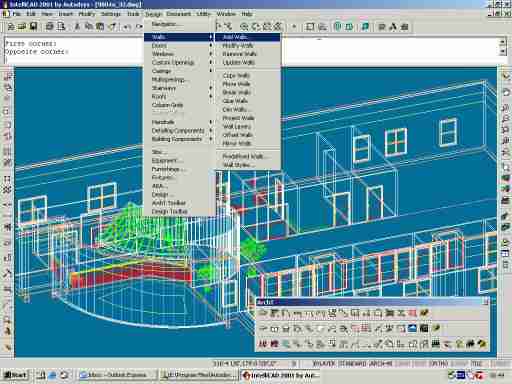
Screen capture of the ArchT design menu.
The specifically supported stages are pre-design massing studies including site representation and rough building placement, conversion to detailed floor plans, design revision and elaboration, generation of dimensioned plans, sections, and elevations, materials lists and specifications. The tutorial provided with the product takes you through these stages for the design of a medical centre, divided up as follows:
Pre-design phase
- Create a building mass
- Adjust the shape of the building
- Add terrain to model
- Add site features
- Create a perspective view of the site
- Create a site section
From schematic to floor plans
- Create a detailed floor plan from the space-planning line diagram
- Add walls
- Area reporting
- Add doors
- Add windows
- Modify the plans
- Copy the first floor to make the second floor and modify it as needed.
Design development – Refine design options
Construction and program requirements become more clearly defined, design options are explored, and schematics drawings are refined to create more detailed plans.
- Modify walls and wall styles
- Generate elevations & sections
Construction documents
Documenting the model typically involves creating plans, sections, elevations, etc., which contain dimensions, tags, notes, and schedules.
- Add a door schedule & tags
- Customize the door schedule
- Add dimensions, detail bubbles, notes
- Arrange and detail plans, elevations & sections to scale on drawing sheets.
Construction administration
The building is now under construction and the project has moved into the construction administration phase, where client changes necessitate revisions to the building drawings and documents.
- Manage change orders
- Track revisions with Multilevel
- Manage changes with overlays
Use existing CAD drawings
Drawings created outside of ArchT using lines, arcs, circles and blocks contain no style data, no 3D model information, and hence no data modeling capabilities. In order to be able to create, say, a door schedule from such drawings, the computer must be able to interpret certain groups of lines as doors. The line drawings must be updated to create multiple views and reports. The tutorial demonstrates the steps for transforming such a 2D drawing into an ArchT model. This mainly involves tracing over the original lines with ArchT tools that snap onto the original geometry.


Screenshots of the ArchT “Utility” and “Document” menus.
Since ArchT produces and stores its data in the form of AutoCAD DWG files whether working in AutoCAD or IntelliCAD, design data produced in ArchT can be accessed directly by any user of AutoCAD or IntelliCAD without ArchT. However, the ‘intelligence’ of the objects will not be active of course. Some ArchT elements are implemented in AutoCAD as custom ARX objects, which will not be properly visible in plain AutoCAD or IntelliCAD, but this consideration does not apply to ArchT data produced with IntelliCAD.
Flexibility
Flexibility is a major aspect of ArchT’s design philosophy Although it provides a comprehensive set of default ways of doing things and representing objects, it also allows most aspects to be done differently if your own ideas or company standards require it. In particular, you can determine which floor-levels, layers, colours, linetypes, and material types to use, and which wall, door, window, and stairway styles are appropriate.
Some architects prefer to design in 2D plan, while others like to design in 3D model. Some prefer to build multi-floor models in a single drawing, while others create each floor in a separate file. ArchT allows for all approaches.
Rendering
Because symbols are built using standard AutoCAD or IntelliCAD 3D entities, they are compatible with all rendering products that work inside of AutoCAD or IntelliCAD or that provide file transfer via DXF or IGES. These products include:
- AutoCAD’s or IntelliCAD’s internal SHADE command
- AutoCAD’s internal RENDER command
- AccuRender 3 external program or AutoCAD add-on
- Autodesk 3D Studio
Although ArchT can work with any rendering package which can render AutoCAD models, it has been specifically designed to work with AccuRender 3 and AutoCAD’s RENDER command in Release 14. You can use predefined materials with those products. The ability to use predefined materials is not available with IntelliCAD.
ArchT appears to provide a very thorough and convenient means of designing and detailing buildings using 3D methods, and in conjunction with IntelliCAD 2001 supplied by the same makers, at a very economical price.


