A reader of CADinfo.Net emailed me recently with the following remarks…”Our problem is this. We get files from customers who want us to create artwork for labels. (We make stick-on labels for equipment etc.) The problem arises when they send us their label design as an AutoCAD DWG file. We open the DWG file with AutoCAD LT 2000. Sometimes it is immediately obvious that something is not right. The label may have lines of text that overlap a bit – that is, some lines are too closely spaced for the size of the characters. More often it all looks sensible, but when we send a proof for approval they complain that the text layout has been altered.”
This reader sent some example DWG files and some screen-grab images showing what they should have looked like. It was clear to me that the label text was being drawn using AutoCAD’s Multi-Line Text option, and that the problem was that the text lines were wrapping to the next line at different words from how it appeared on the originator’s AutoCAD, or running onto, say, three lines when there had only been two originally.
This problem can arise when the recipient does not have the font used by the original author. AutoCAD substitutes some other available font. It can also happen when the original author’s text fonts are slightly different from the same-named fonts on the recipient’s computer.
AutoCAD’s Multi-Line Text uses a text column width that the user defines in terms of Drawing Unit measurements, usually by dragging a rectangle with the mouse. Then the entered text automatically wraps to a new line when the last word won’t fit in that column width. Multi-Line text always uses Windows TrueType fonts, unlike the older single-line AutoCAD text, which can use the old SHX font system (a font system designed for pen plotters that was inherited from DOS versions of AutoCAD). It seems as though you can use SHX fonts in Multi-Line Text but in fact AutoCAD substitutes TrueType fonts that mimic the old SHX fonts. In the case of these labels, proper Windows TrueType fonts were being used because the old SHX fonts would look too crude on a printed label.
 The system should always work predictably when the DWG file is transferred to another computer running AutoCAD if the fonts used are those that are always found as standard on Windows computers. There are a small number of TrueType fonts installed as standard by Windows, and some more that are commonly found if the user also installs Microsoft Office. There are also several TrueType fonts that the AutoCAD installation places into the Windows system. Those include the SHX-mimicking ones referred to, which look rather crude, and several serif type fonts rather similar to the ubiquitous Times Roman, but, regrettably, all rather badly formed.
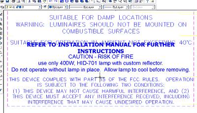
The “non-bolded ” text shown above is being displayed by AutoCAD in the font defined for the Text Style, which is ‘Standard’, defined as using ROMANS.SHX font.
However, when brought into the Multi-Line Text editor, it is seen to have been overridden as a TrueType font. I understand that it was UNIVERS.TTF, but, rather unhelpfully, AutoCAD is displaying the nearest name-match it can find on my PC, which is ‘Universal Math BT.TTF’. Oddly, it has not displayed in that font (which is just as well considering it is all Greek and maths symbols). Instead, because I do not have the specified font, it has reverted to the style defined for the Text Style, ROMANS.SHX, or actually, ROMANS.TTF which mimics it.
 The heavy face text that overlaps the line above (see first image above) has wrapped to an extra line, and spread both upward and downward because it was defined as centered vertically and horizontally. I edited this text to use VERDANA.TTF to make it wider to demonstrate this effect.
The three fonts that you can always guarantee will be present on any Windows computer are Arial (sans-serif), TimesNewRoman (serif) and Courier (fixed-width). Additional ones vary by: version of Windows; version of Office; came with various other applications; or have been obtained by the user in font-packs or off the Web. The above three are the only guaranteed ones. Courier is not usually considered suitable for printed labels and a sans-serif style is generally preferred. So that leaves only Arial, which is basically good for the purpose, except that its characters tend to be squeezed together a little excessively. Some other font may be desired for maximum clarity and good appearance.
 Arial is a form of the long-popular Helvetica, also named Swiss by some font makers. Makers use differing names to avoid copyright infringements, which makes for a lot of confusion. Although the Arial, Helvetica and Swiss fonts have virtually the same character shape, they differ in minute details and more noticeably in inter-character spacing. Those slight differences can add up along a line of text to affect where line breaking will occur.
The example problem files supplied to me were defined to use a font called Univers. The creator obviously had a ‘Univers’ TrueType font on the computer, but we have no idea of its source, and it is not a font that they should expect anyone else to have. There are numerous versions of ‘Universe’ (the original spelling) and ‘Univ’ to be found from various font makers. No doubt they all have slight differences. But no version of Universe is commonly found on Pcs.
In this test case, AutoCAD was substituting Arial (at least on my PC) and not surprisingly, the line-breaks were markedly different from the originator’s design, since Arial is a significantly narrower style. But even if I found a Universe font somewhere, chances are it would not be identical to the original one, and might cause different line breaks.
Where an overlapping lines of text was displayed, it was caused when there were two Multi-line Text blocks one above the other. In such cases the top one generated an extra line because of font-width differences, and overlapped onto the text-block below.
I checked to see if there were any differences in text layout between versions of AutoCAD, by saving as an earlier version, but that proved not to be any problem.
The answer to this problem is twofold.
Firstly, the author of the AutoCAD data must use a font that they know the recipient has in identical version, or else supply the needed font file or state where it could be obtained. Unless the font was obtained from a genuinely free source on the Web, sending the font file with the drawing file would usually involve copyright infringement.
Secondly, the author should not rely on Multi-Line’s automatic line breaking. Either use Single-line Text instead of Multi-Line, or else define the Multi-Line Text so that the column width is a bit wider than it needs to be, and insert hard line-ends manually where desired.
As with any situation where an author designs for final output by another party such as a typesetter or pre-press company, it is always the obligation of the author to ensure that the fonts that are used are also available to the recipient. This is a long-standing situation in the graphic arts and printing trades and applies just the same to CAD work.
AutoCAD was being used in this instance because the labels involved diagrams as well as text. Another technique would be to prepare the artwork for the labels in a vector artwork program such as Adobe Illustrator or Corel Draw, and import the AutoCAD diagrams in DXF form. But the same provisos would still apply regarding multi-line text wrapping and font availability.
Because of this type of problem and the font copyright issue, it has now become common practice to send material to press companies in Adobe Acrobat PDF format. That embeds the font definitions in a locked-up form that avoids copyright issues, and ensures that the result will be as expected. It is also a compact file format that helps in transmission. AutoCAD does not have any PDF output facility, most regrettably. But it can be added by buying either the Adobe Acrobat package or a large format PDF printer-driver, such as that from JAWS Systems in UK (http://www.jawssystems.com). The latter is the cheaper option and also easier to operate. The Adobe option is dearer but much more versatile and has many more ‘tweakable’ options to get the best results, if the user cares to learn a bit about it.
Beware of unexpected changes to Multi-Line Text line wrapping, and font appearance changes, whenever AutoCAD drawing files are exchanged. Always check that the recipient has the fonts you use, and preferably use hard line-ends as well.
Since in some cases, the recipient may prefer to set up their data in an artwork program, and only needs the AutoCAD data for the diagram elements, it may be better to supply just the diagram data in DXF format, and a print of the AutoCAD data to show the text and text format required. In any case, it is always advisable to supply a print (plot) of the AutoCAD data so that the recipient can see exactly what was displayed on the originator’s system. Another possibility is to send a DWF file.


