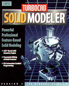
TurboCAD Solid Modeler 2.0 from IMSI is one of the latest ACIS-based parametric solid modeling software packages. TurboCAD Solid Modeler includes the 2D/3D-wire frame CAD package, TurboCAD Professional 5.1, used to create production drawings from the solid modeler. It has a very user-friendly interface, able to be tailored to suit individual needs. Using a single dialogue box, it is possible to fully customize the toolbars, and modify keyboard short cuts and right button menus.
Part modeling inside TurboCAD Solid Modeler is a simple process. After creating a workplane, the user inputs the origin and then, having done this, the 2D objects can be constrained to that workplane. From there it is possible to perform the base operation to create a solid model. The user can create a second part by making a new workplane (or even selecting an existing workplane). TurboCAD Solid Modeler comes with standard ‘quick parts’ that can be used for basic model creation, allowing the user to input the desired sizes and achieve fast results.
 Editing solid models is an equally simple process. Right-clicking the particular component in the history browser makes for easy modification of your model. The feature for re-ordering the model can be dragged and dropped inside the history browser. TurboCAD Solid Modeler also allows you to store your parametric profiles in a library for later use.
Assemblies and Storage
TurboCAD Solid Modeller allows the user to combine parts in assemblies and use 3D constraints to apply relationships between parts in the assembly. It also provides a library folder where parts can be stored for use while assembling the model. In so doing, it gives the user several ways of positioning parts in an assembly. One of the most impressive features is its ability to use standard windows ‘edit’ commands to copy, cut and paste parts into assemblies.
One of the areas that lets TurboCAD Solid Modeler down a little is its method of producing detailed drawings. The user has to export the model into TurboCAD Professional and then do all of the drafting work in a separate package. This means that there is no link between the model and the drawing, which could be a problem for some people. But when you consider the cost of the package you soon realize that this is only a small issue and I think this small deficiency may be changed in the near future.
Data Transfers
TurboCAD Solid Modeler supports a large variety of data transfers. If you wish to import models, you have the choice of IGES, SAT DWG and CCD. For exporting models, you have the choice of IGES, DWG, DXF, STL, SAT and VRML. For importing or exporting a profile, the user has a choice between DWG, DXF, CMX and CPR. It is possible to export views using DWG, WMF, EMF, CMX, BMP, TIF, GIF and PCX. TurboCAD also features a programming API and OLE automation support using Visual Basic, C, C++, Delphi and Corel Script.
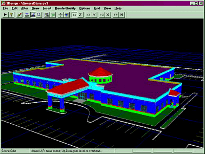
Interactive Rendering Mode TurboCAD Solid Modeler has a built in rendering engine, which allows the user to produce photo-realistic images. To apply materials to a model, the user can drag-and-drop a specific material onto the model from the materials library, which is accessible via the tabs on the history tree. The rendering engine allows you to create scenes, and apply lights, foregrounds, backgrounds and shadows.
When working on a solid model, the user also has the choice of working in interactive render mode, which makes it possible to work on a rendered model. The model remains rendered as you rotate and change views. If the need arises, you have the option of rendering a single viewport or rendering all the viewports.
In Short
I believe that we will hear a lot more about this product in the near future. If you consider TurboCAD Solid Modeler’s low cost, its detailed feature-set and the extremely short learning curve users need in order to become productive, the package represents excellent value for money.
(CAD User – republished by arrangement)


![ViaCAD 2D/3D v9 [Download]](https://www.cadinfo.net/wp/wp-content/uploads/2015/05/41c-4JmS5yL.jpg)


