MicroStation has always been a 3D design application, but it is more commonly used as a 2D “electronic drawing board” – what a waste!
Why Do It In 3D?
Using MicroStation to model objects in 3D is not difficult, especially with the capability built into the latest version. The advantages of creating 3D models are huge – we can virtually prototype our design before a dollar is spent on manufacture. Added to this, problems and solutions that would be invisible in a 2D design often become obvious when creating in 3D.
However, unless we are into Computer Aided Manufacture (CAM), we still need to produce paper drawings. These need to have a number of views, each complete with annotations and dimensioning to precisely define the object for the builder or manufacturer.
The following text will provide step-by-step instructions on how to make use of Sheet Models to document a supplied 3D model. Of course, the same general process can be applied to any model of our own.
Models
Documentation of designs has suddenly become much easier with the introduction of MicroStation V8. MicroStation now supports Models, including Sheet models. Now the drawing process is even easier than producing the original design model. Since this concept is fairly new to MicroStation, a little explanation is appropriate.
Models in DGNs are sets of Design Elements (such as lines etc.) that are unique to that model. A single DGN may have many Models, but only one Model can be active at any time. There are Design and Sheet type models, with Design models containing the actual designs and Sheet models the “paper” drawings.
In other words, Sheet models are used to compose the final drawing, mostly from elements referenced from the Design model(s). Annotations and dimension elements are placed in this Sheet model, along with borders (usually referenced), title blocks (maybe cells) etc. The actual printouts are created from Sheet models.
The First Step
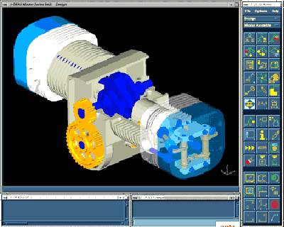
 Files for the following examples are available for immediate download. They are “zipped” into TentFrame.ZIP, which will expand to create Tent Frame.dgn, along with a cell Library and a couple of border DGN’s. Only the DGN’s are needed for the following examples, but the cell library may be interesting to experiment with. The sample design model is of a set of tubular steel demountable framework components for a hire company party tent. This model was chosen to be complex enough to require multiple views, but simple enough to complete the exercises fairly quickly. A rendering of the completed frame is shown below, the model for which is included in Tent Frame.dgn.
We will start by downloading TentFrame.zip and expanding it into any convenient folder. If you would prefer to use the following instructions to create drawings from your own model, skip straight to “Creating a Sheet Model”; otherwise we will start by examining the supplied Tent Frame.dgn.
The Supplied 3D DGN File
Assuming that you have Tent Frame.dgn already unzipped:
- Start MicroStation V8 and open Tent Frame.dgn. At this stage, you will find only two view groups available from the View Group option menu (usually docked on the bottom-left of the screen). Each of these view groups opens its own model.
- Choose the Assembly Views view group.
- A rendered view of the complete frame assembly opens. This was created from appropriately rotated and accurately placed cells of a number of sub-assemblies, which in turn were created from the design model. This model is included to provide an overview of the design.
- Window in on details of the assembled frame and dynamically rotate the view to examine the design and familiarise yourself with it. There is a saved view named “Perspective” to restore the view if desired.
- Choose the Model Views view group, window in on the various components and sub-assemblies. Try turning on Constructions in the View Attributes dialog and noting the construction class elements used to create the 35 and 40mm rectangular hollow sections etc.
Hint: When selecting the view for dynamic rotation, manually snap to a keypoint on the model and accept this as a point to rotate about.
The Model model contains only the components and the sub-assemblies; the Assembly model has copies of the sub-assemblies in sufficient number to construct a complete frame assembly. For example, there is only one horizontal frame in the Model, but there are seven of them in the Assembly.
The DGN was created with metric units, but this can be changed to feet and inches under Settings > Design File without any of the geometry changing actual size.
Creating Sheet Models
We have everything needed to complete a full set of drawings. The following examples use either A4 or Letter sheets (both portrait and landscape), with the supplied drawing borders referenced. The borders are little more than blocks with active points for snapping the plot defining fence, so you may prefer to use border dgn’s of your own. The examples use a number of small sheets, which provides plenty of practice, but feel free to use larger paper sizes and fewer sheets. We will start by creating a simple Sheet model of the perspective view of the model.
1. Make sure that the Primary tool box has the Models tool icon displayed – if not, right-click the border of the tool box and check the appropriate check box.

2. Select the Models tool, then select the Create a new model icon from the Models dialog.

3. Choose Sheet from the Create Model Type options, Name: Sheet 1 Description: Whole Assembly. The remaining settings should match those shown in the illustration.

4. Click OK and the Create Model dialog will close and an empty single view in the new model will open.
By default, Sheet views have a white background and Model views have a black background. Now we have the first sheet model ready for use, we will reference a border into it. Attaching References
The first reference we will attach is a border. We will attach this at 1:1 scale, so we will need to scale down the assemblies as we reference them in. This is not the only way to do it, we could choose to scale the border and reference in the model at 1:1. Both systems have their advantages, but using “paper size” is probably the most practicable when we need to use multiple scales. Make your own judgement when we have finished the examples.
- Select the Attach Reference tool from the References tool box (turn on if necessary).

- In the Attach Reference dialog, select the supplied DGN A4 Landscape border.dgn or Letter Landscape border.dgn, click OK.
- The choice of A4 or Letter will depend on the paper size available in your printer.

- Click OK to accept the defaults (as illustrated) in the Attach Reference Settings dialog.
- Fit the view to reveal the extents of the border.
Now we will attach a perspective view of the assembled frame. This view is available as a saved view in the Assembly model of the active DGN.
- Select the Attach Reference tool from the References tool box (as before).
- In the Attach Reference dialog, select Tent Frame.dgn (the active DGN), click OK.
- Select the Assembly model, the Perspective saved view and the scale 1 : 18 in the Attach Reference Settings dialog (as illustrated); click OK.

- Initially position the reference with a data point approximately at the center of the border.
- Use the Move Reference tool to re-position the reference as required.

We now have a sheet view that is ready to print. If you would like to do this right now, here are the instructions.
Printing from a Sheet
This sheet model has only one drawing sheet referenced to it, but we could have moved this sheet aside and attached more borders and views. However, we will only have one drawing sheet per model for this exercise, as it can make finding the sheets easier in the future.
To print this out, it is simply a matter of first defining the print area (note the active points for manually snapping a fence block). We can then set the printing attributes and send it to a Letter or A4 printer, which we will assume is attached to our machine as the default Windows printer.
Since the border is actual “Paper” size, we can set the scale to 1 : 1 (it will be slightly less than this when the active points are used to place the area defining fence). This sheet is mainly pictorial, so the fact that we set the scale to 1 : 18 when we referenced the Assembly model earlier is of little importance.


Sheet Model Sheet Models With Dimensioning and Text
The next sheet model we will create is to have top views of two components of the frame, referenced at full size. We will position them on the sheet, then add dimensioning and text.
Create a Drawing Sheet for the Horizontal Socket Components
- Create another sheet model in the same manner as in the “Creating Sheet Models” exercise, except this model will be named Sheet 2, with the description Horizontal Sockets.
- Reference the same landscape border DGN as before.
- Select the Attach Reference tool from the References tool box (as before).
- In the Attach Reference dialog, select Tent Frame.dgn (the active DGN), click OK.
- Select the Model model, the Lskt Top saved view and the scale 1 : 1 in the Attach Reference Settings dialog, click OK.
- Position the socket within the border.
- Repeat steps 4, 5 and 6, except this time use the saved view Uskt Top.
Now we have two components referenced, we can adjust their positions (Using the Move Reference tool) within the border as necessary to compose a drawing sheet.
Placing Dimensioning and Text
We will not go into any great detail about dimensioning and text placement, as the techniques are exactly the same as for 2D drawings. The attached dimension styles are metric, but this may easily be changed under Element > Dimensions if you wish. You may also import dimension styles of your own.
- Make the Dimension Level active.
- Select the Dimension Size with Arrow tool, choose 1:1 (General Purpose) dimension style.

- Place dimension elements as required.
- Note that we can place the associated dimensions as if we were working in a simple 2D design, no need to concern ourselves about depth, as we would if we were dimensioning in a conventional 3D model.

- Select the Place Text tool, choose the General 1:1 text style.
- Make the Annotations level active.

Component details
This sheet will show the ends of the long horizontal and roof frame tubes. The saved views were created to only display the required detail, with the saved view of the roof frame rotated to make it appear horizontal.
- Create a third sheet model in the same manner as in the “Creating Sheet Models” exercise, except this model will be named Sheet 3, with the description Horizontal and Roof framing ends.
- Reference the same landscape border DGN as before.
- Reference Tent Frame.dgn (the active DGN), selecting the Model model and the Horiz End saved view. Leave the scale as 1 : 1.
- Reference Tent Frame.dgn (the active DGN), selecting the Model model and the Roof End saved view, scale 1 : 1.
- Compose the components within the border.
- Make the Dimensions level active and dimension the components, using both the attached dimension styles.
- Make the Annotations level active, place text as required, using both the attached text styles.

More Complex Referencing and Dimensioning
The next sheet will show a typical roof corner socket. In the model, this is rotated both vertically and horizontally with respect to the design X and Y axes. However, the saved view we will reference has been rotated to make the component representation easier to follow. We will also add some of our own geometry in the sheet model.
- Create a fourth sheet model in the same manner as in the “Creating Sheet Models” exercise, except this model will be named Sheet 4, with the description Roof Corner Sockets.
- Reference the same landscape border DGN as before.
- Reference Tent Frame.dgn (the active DGN), selecting the Model model and the Cnr Skt saved view. Set the scale to 1 : 1.
- Position the component within the border.
- With the Annotations level active, add the broken line extending the “birdsmouth” cutout, as shown in the illustration below.
- Dimension the component, using both the attached dimension styles.
- With the Annotations level still active, place text as required, using both the attached text styles.

Presentation Plus!
The next sheet will present scaled sub-assemblies, with the hidden geometry removed.
- Create a fifth sheet model in the usual manner; this model will be named Sheet 5, with the description Top Upright Assembly.
- Reference the appropriate Portrait border DGN, either A4 Portrait border.dgn or Letter Portrait border.dgn.
- Reference Tent Frame.dgn (the active DGN), selecting the Model model and the TP Top saved view. Set the scale to 1 : 5.
- Reference the Tp Iso and Tp Front saved views from the same model, also at a scale of 1 : 5.
- Position the sub-assemblies within the border as required.
- Dimension the side view, place text and additional linework as required.
Note: There is no need to do anything about the scale – the dimensions are actually associated with the Design model, not the geometry as it appears in the Sheet model. This is one of the most powerful features of the “Sheet Model” facility.
Select the Set Reference Presentation tool from the References tool box, set the Presentation to Hidden Line.


8. Identify each of the sub-assembly references, accepting each one with a data point, update the view.
The views will now appear with “Hidden Line” or “Visible Edges” presentation. Now, sheet 3 would benefit from this presentation…
More Hidden Line Views
The next two sheets have the views of the lower upright assemblies.
- Create a sixth sheet model in the usual manner, this model will be named Sheet 6, with the description Lower Rear Upright Assembly.
- Reference the appropriate Portrait border and Tent Frame.dgn, selecting the Model model and the BRP Top saved view. Set the scale to 1 : 5.
- Reference the BRP Iso and BRP Front saved views from the same model, also at a scale of 1 : 5.
- Position the sub-assemblies within the border as required.
- Dimension the top and left views; place text and additional linework as required.
- Select the Set Reference Presentation tool from the References tool box, set the Presentation to Hidden Line and convert each of the sub-assembly references, as in the previous exercise.

- Create sheet 7 as for sheet 6, except use the Lwr Top LHS, Lwr Frnt Top RHS, Lwr Frnt Left Iso and Lwr Frnt Side saved views.

Various Scales on One Sheet
The next sheet model will combine full-size details with a scaled down component. As mentioned earlier, this is no problem, the dimension elements always see the actual model, not the scaled reference geometry.
- Create an eighth sheet model, named Sheet 8, with the description Upright Components.
- Reference the appropriately sized Landscape border.
- Reference the active DGN, selecting the Model model, the Mskt and the Foot Top saved views. Set the scale to 1 : 1 for both.
- Reference the Upright saved view from the same model, at a scale of 1 : 10.
- Position the sub-assemblies within the border as required.
- Dimension the views, place text as required.

- Create sheet 9 as for sheet 8, except use the Roof Cassy saved view at 1 : 2 scale, Roof Core, Cap and Roof Skt saved views at 1 : 1.
- Change the Presentation of the center assembly to Hidden Line.

That’s it, folks! Now you have nine drawing sheets ready for printing in the usual way. The starting point for this type of drawing composition is the creation of saved views for all of the components to be detailed. To save time, all of the saved views were created for you here, but this is a simple process, well within the capability of most MicroStation users. Much can be learned by opening the Model model and applying the saved views one at a time, noting the shape of the view, levels turned on etc. Once the model is created, the rest is pretty much 2D, as evidenced from the exercises in this article.
Note: The publication of the tent frame design in this article is purely intended for an exercise in creating drawings. The design is copyright and any drawings thus created are not to be used to manufacture actual tent frames.


