If you are considering changes to the coding that you use to define your objects, ultimately there need not be as many problem drawings created. But in the interim, what can you do to make it easier to work with the old drawings?
To upgrade a drawing, you need to translate the coding systems that have been used in the non-conforming drawing to the ones you need. There are two fundamental differences you have to deal with:
- Two kinds of coding systems used. That is, one kind of coding uses cad properties to represent plotting characteristics only and the other kind represents the objects where colors, linetype names, and plotstyle names are variables that can have their own definitions in the form of lineweights, linetype patterns, and other plotting characteristics.
For example, a color is used explicitly to represent a lineweight rather than an object, and a linetype name is used explicitly to represent a dash-dot line pattern rather than part of an object.
The difficulty with lineweight and pattern codes is that there are not enough unique definitions, and the same definition has to be used for another object. You can not convert all of the lineweights or linetypes of a given definition, but you need them to be changed for certain objects. You can automate the conversion of colors and linetype names representing the object to represent lineweights and patterns. But to convert lineweight and pattern codes into an object code, you have to manually select which objects to apply the code to. - Varying extents in the classification of objects. That is, cad properties are coded more specifically to represent only one kind of object versus being coded more generically to represent many kinds. For example, you can automate the conversion of many more specific layer names to more generic ones. But to change one to many, you have to manually select which objects to apply the new name to since those objects have been given no method of recording more specific identification.
Acting on the answers to the following questions helps to reduce the muddle and determine a process that will work for you until more companies adopt compatible systems:
- What is essentially IMPORTANT, and what can be LEFT as it is?
- What kind of system should your company use?
Remember that when you use object classification, you can use the classifications as the basis for all of your sub-systems. That is, there is a standard linetype name, color, plotstyle name, and layer name defined for each of the objects. This enables you to uniquely identify the object for automated conversion of any code while the definitions can be used repetitively. The extent of classification can be applied in varying degrees for the sub-systems. The plotstyle names are the most specific and the others can be as specific or generic was you need.
Here are some point by point methods for overcoming the difficulties when you encounter non-conforming codes:
General Rules
- If you are mostly a creator of drawings for delivery TO others, the extent of classification that you employ should tend to be more SPECIFIC than what the other companies use. Conversely, If you work with drawings received FROM others, the extent of classification that you employ should tend to be more GENERIC than what the other companies use.
- The definition of a cad property that is used as a code has to be unique. You cannot use that definition for anything else. For example if color 30 is used as a major object code for a framed wall, and color 150 is used to define a concrete wall, the colors have lineweights but you can not use those colors to represent lineweights. You CAN use color 31, 33, 35, and 37 as lineweight codes for framed walls.
- When you convert name codes to a more generic system you should allow consideration for changing the name to a more specific classification of the major class in the new system, and then define a new resource (e.g. a new layer, linetype, or plotstyle) under that name. In the least, you should flag those codes so the receiver of the drawing can consider adopting a more specific code.
Part 2 discusses answers to the questions posed above, and offer some special solutions for changing symbol blocks, linetypes, colors, layers, plotstyles, textstyles, and dimstyles.
The first part of this document outlined two fundamental differences that cause problems when you need to convert old drawings to new setup standards namely…
- Two kinds of coding systems used, one that represents the design objects, and the other that represents plotting characteristics only.
- Varying extent in classification.
It also defined “3 General Rules” to make things easier when you encounter non-conforming codes:
- If you are normally a sender of drawings, then tend to use more specific classification, or more generic if you are mostly the receiver.
- The definition of a cad property that is used as a code has to be unique. Use colors and linetypes to represent objects and ensure that no color or linetype name is used to represent more than one major object class.
- Add a more specific classification as a suffix to a more generic name, or flag the name with a unique prefix so the receiver of the drawing can consider adding a more specific category to their standard.
This part answers three questions that will help you to determine processes for dealing with problem drawings, and offer some special solutions for changing symbol blocks, linetypes, colors, layers, plotstyles, textstyles, and dimstyles:
- What is essentially IMPORTANT, and what can be LEFT as it is?
- What kind of system should your company use?
- Are the new codes going to be more SPECIFIC or more GENERIC?
Symbol Names
- Important: Symbols always represent the objects that you deal with in your field of practice and they tell the reader of the plan what the design objects are. It is important that the old symbols are compatible with the new symbols that will be used. You must either have both shapes listed in the symbol legend, or change the existing symbol blocks to match the ones that will be used for new work.
- Make the classification of your objects and the symbol block names you use conform to General Rule “X”. If you are a sender of drawings, then use more specific classification, or more generic if you are the receiver.
- If the new symbol blocks are more generic, consider Rule “Z”. Add more specific symbols, or identify the symbol blocks with a unique prefixes to the generic names so that the receiver of the drawing can consider adding more specific symbols to their standard.
Solutions:
- Automate the conversion of the existing block names to the new block names. If a new symbol block is more specific, automate the change to the name of your most widely used equivalent and add a prefix to identify it for more specific changes. You will have to manually select which insertions need to be changed and then replace those insertions with the more specific symbol block.
- Redefine the block definitions by importing the new symbol blocks into the drawing. If the new symbol blocks have attributes, accept them as blank fields when you import them. Although the block’s attributes are associated with each block insertion, they are stored as separate entities in the drawing. The existing block’s attributes will remain regardless of whether the new symbol blocks have attributes or not.
Linetype Names and Colors
- Important: The linetype patterns and colors identify what lines are and if you are using color dependent drawings, the color’s lineweight conveys the importance of what is drawn. It is important that you change the linetype names and the colors.
- Preferably, you need linetype definitions for the major object classes AND for patterns. Similarly, color definitions are needed for the major object classes AND for lineweights, densities, and text heights. Make the classification of objects and the kind of color codes and linetype names you use, conform to both General Rule “X” and General Rule “Y”. If you are a sender of drawings, then use more specific classification, or more generic if you are the receiver. Use colors and linetype names to represent objects and ensure that no color or linetype name is used for more than one object class.
- If the new codes are more generic, consider Rule “Z”. For linetypes, add a more specific linetype, or flag the name with a unique prefix so that the receiver of the drawing can consider adding more specific linetypes to their standard. For colors, add a more specific color code or flag the object with an unused color.
Solutions:
- Automate the conversion of the existing linetype names and colors. If a new linetype code is more specific, automate the change to the linetype name of your most widely used equivalent and add a prefix to identify it for more specific changes. You will have to manually select which objects need to be changed to more specific names, and then make those changes manually. If a new color code is more specific, automate the change to an unused color to identify it for more specific changes, or use one of the tints in the same hue as your most widely used equivalent.
Named Plotstyles
- Important: Named Plotstyles represent each of the objects that you deal with in your field of practice. The named plotstyle is a variable that defines the linetype, color, lineweight, and screening properties for named objects and conveys what lines are on the printed output. It is important that you change the plotstyle names.
- Make the classification of your objects and the plotstyle names you use conform to General Rule “X”.
- If the new codes are more generic, consider Rule “Z”.
Solutions:
- Automate the conversion of the plotstyle names. If a new plotstyle code is more specific, automate the change to the plotstyle name of your most widely used equivalent and add a prefix to identify it for more specific changes. You will have to manually select which objects need to be changed to more specific names, and then make those changes manually.
Layer Names
Importance depends upon whether layer names are also being used to define specialty of cad properties. That is, additional layers are being used to represent the same object, but with a different linetype or lineweight.
- Assuming you do not use additional layer names to the define specialty of cad properties, pre-existing layer names can be left as they are because they can be made to plot correctly, and you do not have to use these layers for new drawing work. Layers NEED ONLY (my emphasis) affect plotting in cases where you want some, but not all of the objects on a layer to be plotted.
- Make the classification of your objects and the layer names you use conform to General Rule “X”.
If you avoid using additional layers to define specialty of cad properties, your layers will only represent objects, and the difficulty associated with using 2 kinds of coding systems does not arise. If you use layers to represent cad properties as well as objects, the difficulty is immense. There will be an enormous amount of work converting to and from other systems.
In my opinion, trying to use layers to represent cad properties is not a sensible practice, and it will frustrate the evolution of universal standards for layer names.
If you need all of the pre-existing layers to conform to your standard and the new layer codes are more generic, consider General Rule “Z”. Add a more specific classification as a suffix, or flag the name with a prefix.
Solutions:
- Automate the conversion of the layer names. Unless you need to turn off only some of the objects, the difficulties associated with varying extents in the classification of objects need not arise. Pre-existing layer names that are more generically classified can be left as they are, while your new work is placed on your more specific layers.
- If you are using additional layer names to the define specialty of cad properties and the new layer code is more specific, automate the change to the layer name of your most widely used equivalent and add a prefix to identify it for more specific changes. You will have to manually select which objects need to be changed to more specific layer names, and then make those changes manually. Textstyle and Dimstyle Names
Importance of textstyles and dimstyles depends upon whether there are non-conforming fonts, width factors, tick marks or arrowheads, or non-conforming placement of text relative to a dimension line. The level of difficulty in converting them depends upon whether text height has been defined in the textstyle rather than by the text object, and whether different combinations of dimvar settings have been defined in the dimstyle instead of using the dim overrides.
- With the exception of the need for conforming fonts, width factors, tick marks or arrowheads, and placement of text relative to a dimension line, the existing textstyles and dimstyles can be left as they are. As with layers, these styles need not be used for any new work.
- It is not necessary for your standard textstyles and dimstyles to be defined for any purpose other than for different fonts, and one or two kinds of arrowhead. In most cases you need only 1 or 2 standards for textstyles and about 3 standards for dimstyles. If this practice is followed, the difficulty with different kinds of systems will not arise. Changes can either be automated or done manually during work in progress. However, you must be careful that existing objects are not updated for settings such as scale, linear scale factor, extension line suppression, or any other setting that is specific to each insertion.
- If textstyles are defined for each of your text heights and drawing scales, and if the combinations of dimvar settings are defined in the dimstyle, the level of difficulty associated with automated conversion of textstyles and dimstyles is severe.
- Varying extents of classification do not apply to textstyles and dimstyles except as referred to in b) above.
Solutions:
- If textstyles are classified only for the font and the width factor, and the dimstyles are classified only for the textstyle and arrowhead used, you can simply import the new textstyles and dimstyles. Then, use a conversion utility to automate changes from the old textstyles and dimstyles to the new ones for each of the objects in the drawing.
If existing textstyles are defined for each text height and drawing scale and existing dimstyles are defined for combinations of dimvar settings that vary by the inserted object (such as dimscale and extension line suppression), the problems associated with ridding the drawing of the existing styles make it impractical to do so. In this case, you will need to:
- Import the new textstyles and dimstyles for new work and retain the existing textstyle and dimstyle names in the drawing.
- Use a text change utility to change the fonts and the width factors in the existing textstyles. Manually redefine each of the existing dimstyles for the textstyle (by changing the dimtxsty dimvar), the arrowheads (by changing the dimblk, dimblk1, and dimblk2 dimvars), and placement of text relative to the dimension line (by changing the dimtad and dimtvp dimvars). You will not be able to rid the drawing of all of the old textstyle and dimstyle names.
Part 3 will summarize my views and recommendations on the kind of cad system you need to enable effective solutions to deal with all of the issues in non-conforming drawings, and, by evolution, define true industry standards that will that will reduce the number of times you have to deal with problem drawings.
Earlier parts of this article outlined 2 fundamental differences that cause problems when you need to convert old drawings to new setup standards, defined some general rules to make things easier when you encounter non-conforming codes, and discussed some processes for dealing with problem drawings. I will now recommend the kind of cad system that enables effective solutions for overcoming the difficulties with non-conforming drawings and through the exchange of drawings, provide the synergy to establish true industry standards that will reduce the number of times you have to deal with problem drawings. Specifically, the objectives are:
- How to best deal with the different kinds of coding systems and variations in the extent of classification used.
- To foster development of a more uniform standard of practice among firms engaged in the same line of work, and be able to automate the conversion of drawings as much as possible where standards differ. Before achieving this true industry standard, we need to lay out the underlying assumptions (principles) that dictate it, and the reasons for these assumptions.
We must have a common understanding of what we mean by the word “standard”. Is it a protocol to always be followed and endure for all time? I think not because when that is the case, you become locked into using antiquated methods and are unable to take advantage of new technology and improved ways of doing things. Rather, it is “A protocol found most useful and best by the majority of practicing professionals at the current time”. In the building industry (AEC work) practicing professionals should include all the professionals who have a need to use the drawings, but may only include the people inside your own firm. So when we use the word “standard”, it must be understood as “Current Operating Standard”.
During Part 1 and Part 2 of this article, I drew considerable attention to whether you are the creator (sender) of drawings to be re-used by others, or you are only the re-user (receiver) of drawings. But given that operating standards have to be upgraded from time to time to accommodate new technology, then almost everyone is a creator of drawings to be re-used by others eventually. Unless the drawings are never to be re-used (and one ought not plan for or assume this), older drawings will always need to be upgraded to current operating standards sooner or later. So when we are determining cad standards, we should assume that we are the creator of drawings for re-use by others. That means you need to develop your classification to a somewhat greater degree than is currently the normal. As you will see later on, you will only need to use the full extent of your classification for your plotstyles.
Lineweights should not continue to be tied to color now that there is an independent lineweight property available. Only the creator of the drawing knows the degree of contrast needed to convey the designer’s intent, and so the correct lineweights should be applied directly as objects are drawn. When necessary, lineweight settings can be changed or overridden by the object as I will explain later.
Don’t assume that you will be creating layers for everything. A layer offers a variable that is convenient for changing lineweight, color, linetype, or plotstyle, but so does your linetype and your plotstyle. While many of your object codes may be synonymous with layers, it is not necessarily what you want in all cases, and it won’t always be so in the future. In any event, the fact that other methods are even available means they will be used on occasion, and so you need a way to deal with those methods.
Defining your coding systems and classification
At the highest level, use the same denominator for ALL of your coding systems, rather than having some of the codes representing objects and some for plotting characteristics (e.g. lineweights and linetype patterns). This means you develop an object code independent from your layer code that classifies all of your design objects. It is your most elementary code which governs all. It defines all of your sub-systems and the definition of all cad properties, including layers. This primary code will be synonymous with your plotstyle code which is defined in your named plotstyle table (*STB). I’ll explain more about the use of that later.
Each named object that you define has a standard plotstyle, color, lineweight, linetype, and layer.
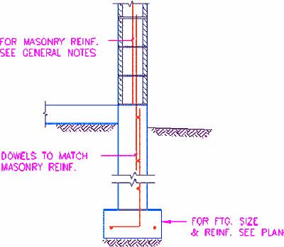
For example, the linetype code represents the object class depicted by the line. The linetype for a wall is “Wall-??” (not “Continuous”), a foundation footing is “Footing” (not “Hidden”) and the linetype name for a grid line is “GridLine” (not “Phantom”). Use your linetype as a variable. For a footing to be demolished, you may need a linetype such as “DFooting” that has a pattern definition of “Dot2”. When you need to convert the linetype, you can convert the “Wall” and “Footing” linetypes to something else which may or may not have the same pattern definition. You can’t automate the conversion of “Continuous” or “Hidden” because such codes will have been used more than once and for all sorts of different applications. The sub-system for linetypes will be less encompassing that the overall object code. The linetype won’t need to distinguish between proposed and existing work. That is distinguished by lineweight on paper and in the computer, by the default lineweights assigned to separate layers for proposed and existing objects. The defaults can be overridden (if needed) by the lineweight setting in the plotstyles for proposed and existing objects. The object code (and corresponding plotstyle name) has a classification for each variation, where the linetype code, color code, and the layer code can be classified to a lesser degree.
The color code represents your major object classes for easy visual recognition. Because lineweights are applied directly, color can be used more freely to represent your major object classes and it also helps you in other ways too.
For example, if you are still using color dependent drawings, developing an object code for color will assist you in the transition to Named Plotstyles. Once you have used colors to represent objects, you can put your naming convention for plotstyles into practice using tools that apply named plotstyles according to color. The plotstyle can also be changed in the same manner during development of your system for named plotstyles. The object code for color will also allow you to change lineweights using tools that apply lineweights according to color. For example, when you are converting a contract drawing to an as-built drawing, the heavy lineweights of all the proposed objects need to be changed to existing objects with lighter lineweights. Where you have set color by object for objects on the same layer, the color code provides the means to associate the desired lineweights for objects on the same layer as well as the new layer lineweights.
The layer code primarily represents the object groups for display, where each of your object groups (or assemblies) will need various layer names. The layer names may or may not be classified in the same way, or to the same extent as your object code and your named plotstyles. The layer property defines a default plotstyle, color, lineweight, and linetype to a layer, but the defaults may or may not apply for all of the objects on that layer.
The object properties for plotstyle, color, lineweight, and linetype are used to override the default layer properties when variations are needed.
The linetype library (i.e. the linetype definition file) defines the linetype pattern to be used for each linetype.
The default plotting characteristics for each plotstyle are set to “By Object Property” in your standard plotstyle table. The objective here is that anyone re-using the drawing avoids having to use the designer’s plotstyles to define the linetypes and lineweights to convey the designer’s intent.
It is important that you reserve your plotstyle definitions to be used as overrides when you are unable to automate conversion or you want to over-ride the original intent temporarily.
When objects on the same layer need different linetypes and lineweights, your object linetypes and lineweights will govern in the 1st instance rather than making it mandatory to have to change the plotstyle name.
For standard operation, retain your plotstyle definitions for overrides that you can use in special cases when needed. Your cad properties are set in the drawing so that the standards are familiar, you can draw and plot what you see, and others can plot the drawing without your plotstyle table. Use another table where,
- automated conversion is not possible for some objects, and
- in the normal course of your work, you need special presentations with alternate lineweights and some color highlighting, When you need to change the output then you retain the ability to define settings that will override the settings in the drawing for some of the objects. Look ultimately, for named plotstyles to become your industry standard of classification for design objects, where you can set up special plotstyle tables for localized applications.
Use only 1 to 3 standard textstyles that are coded only by the font and the width factor, with all of the text heights set to zero. Having codes of this nature makes it possible to convert them and makes the textstyles easier to use in programs for automated text entry.
Use standard dimstyles coded only by its general application and the type of arrowhead used, with the scales (dimscale) and linear scale factors (dimlfac) set to 1.0. This simplifies the variety of dimstyles for conversion and makes the dimstyles easier to use in programs for automated dimensioning. For example, you need only one dimstyle with your standard arrowhead or tick mark for regular dimensioning, maybe one that displays alternate units, and one that displays tolerances. Define the dimvar settings in the drawing unit that you use most. Additional sets of the same standard can be created for different drawing units, but you should use the overrides for all the settings that vary with the insert, such as scale, extension line suppression, and the linear scale factor for insertions in paper space. Make some toggle buttons to turn the dimse1 var ON and OFF if you do not like using the command prompt. With the productivity tools available today, there is no need to have separate drawings for different drawing units and scales.
Maintaining the “Current Operating Standard” and automating conversions
Create synergy through the exchange of drawings that will foster greater uniformity and keep your standards up to date.
When converting to new classifications that are MORE GENERIC, use a name that retains the more specific classification by adding a descriptor following the new generic name, and then automate the changes with a conversion utility. The “re-user” of the drawing can then consider adding a more specific category to their standard, or automate a further change to the generic name.
When converting to a new classification that is MORE SPECIFIC, identify (flag) the code that differs in classification using the name of the most widely used equivalent with a prefix in front, and automate such changes with a conversion utility. In this way, the receiver of the drawing can make a decision on whether they need the more specific classification. If they do, they can easily select the desired objects from within the group of objects identified the flagged code (name) and change them to the new code manually, or automate a further change to some other name.
To develop true industry standards and to maintain those standards to accommodate new technology you must be able to,
- identify and communicate the differences on a day to day basis between other professionals in the your industry, and
- be in a position to make informed decisions to modify and upgrade your operating standards.
Because design objects don’t vary in practice, the object code gives you a common denominator for mapping existing properties to new properties. Your use of linetype names and colors is changed from pattern codes and lineweight codes to variables with definitions that you can freely define to suit local requirements. The desired plotting characteristics are applied by loading your own linetype library and by using an alternate plotstyle table.
For your own standards, ensure that no color or linetype name is used to represent more than one major object class. Of 255 colors available, there are 24 major groups in the various hues, 2 sub-groups of 5 (one light and one dark) within each major group, 5 colors available in each sub-group, and 15 random colors that can be used as codes. Linetype names are unlimited. Either of these object coding systems can be converted to a pattern and lineweight code if that is desired.
Object Ids will become incorporated internally in the software for the most consistent and major object classes the software is designed for. But at the application level, you will continue to need specialization to deal with interaction between multi-disciplines and other fine tuning. User defined coding systems for localized requirements are still needed as well. Billions of dollars are lost each month in terms of production, stress, and frustration from having to deal with non-conforming cad drawings. While it takes considerable planning to organize your cad resources in the best manner for your operation, the results well worth the investment. In my opinion, the benefits outweigh the investment tenfold, not only in terms of increased wealth for your own company, but for the economy in general.
Originally published in S-MAN E-NEWS by Softco Engineering Systems. Re-published by permission.