A frequent need in CAD is to use a set of pre-drawn symbols, such as schematic symbols in electronics or piping. Some CAD products have special provision for symbol libraries and provide a system for selecting items from the libraries by picking from illustrations of the items. Usually the sets of symbols are stored in some special file format as a library, and there may be separate libraries for various fields of work.
In AutoCAD and IntelliCAD symbols take the form of Blocks and no ready-made libraries are supplied with the system. Creating blocks for symbols is quite easy, but there are some confusing aspects and some options for how to organise blocks into libraries of symbols.
Blocks
There are two types of Blocks – internal and external. In IntelliCAD, the former are just called Blocks and the latter are called External File Blocks. You need to understand the following background information, otherwise the use of Blocks can be confusing.
- Internal Blocks are defined within the drawing file that they are used in, and therefore can only be used directly in that drawing. However, IntelliCAD does offer a way of copying Internal Blocks directly from other drawings.
- External File Blocks are saved as separate DWG files and take exactly the same form as any drawing file, except they are usually small and have an insertion base point defined. They can be inserted into any drawing, and so are more obviously usable for symbol libraries.
When Blocks are defined within a drawing (Internal Blocks) they are not visible until inserted into the drawing. Each block has a name and the Insert Block command’s dialog box has a drop-down list of block names found within that drawing. When a block is inserted, the only data added to the drawing is the insertion point, the block name, its insertion x & y scales and its insertion rotation angle. The visible objects that comprise the Block are displayed in-situ but the data for them comes from the single Block definition stored invisibly ‘behind the scenes’.
Hence if you insert the same block 20 times in various locations in the same drawing, there still remains only the one set of data, stored in the block definition. Multiple insertions do not increase the drawing data size, whereas copying the objects that number of times would greatly increase the data size of the drawing file.
An inserted block appears as a set of drawing objects that are grouped together and the individual lines and arcs that make up the inserted block cannot be individually selected, deleted or moved. If you pick one line in an inserted block, it selects all objects in the block. You cannot alter an inserted block, unless you Explode it into individual objects, when it ceases to be a block insertion. The Explode command copies the data objects from the Block definition to the location of the block insertion, hence adding to the size of the drawing file.
Creating Blocks
To create a Block definition within a drawing, draw the symbol, then use the Tools, Create Block command., or from IntelliCAD explorer, pick File, New, Block. The sequence of prompts that appear differ slightly. When done from iExplorer, the block name is automatically supplied, in the form like “NewBlock1” and you don’t get an opportunity to give it a name of your choosing. You can of course later rename it by Windows Explorer.
Example Create Block prompt sequence –
: _BLOCK
Name for new block, or ? To list existing blocks:
(type-in new name, e.g. fireplace2, unless auto-supplied)
Insertion point for new block: (Shift-right-click, pick e.g. Midpoint) _MID
Snap to midpoint of: (pick)
Select entities for block: (pick 1st point for a window selection)
Opposite corner: (pick 2nd pt)
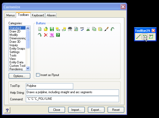
Entities in set: 29
Select entities for block: (press enter)
This asks you to give a name for the Block, and then to pick a point that will be the reference point in the block, that will be placed at the specified insertion point when inserting the block. Usually, this point will be on some feature of the symbol, or at a centre-point etc. usually you will need to use entity-snap to pick it. The example prompts above and illustrated here show a fireplace symbol being selected with a midpoint snap point at its rear-centre as the insertion handle.
Then it asks you to select the objects for the Block. This is usually done by window. When you press enter to finish, the selected objects vanish. They are now stored in the invisible Block definitions area of the drawing file. If desired, you can copy them back as was, without affecting the new Block definition, by typing OOPS. (strange but true!), or you can insert them back to the same place as a block insertion.
Inserting Blocks

Selecting a block already defined in the current drawing.
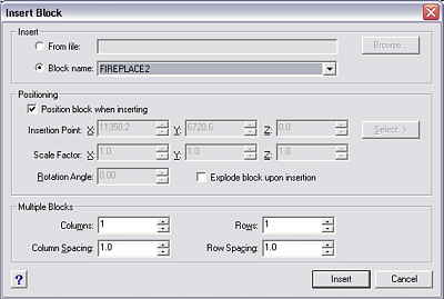
To insert a Block use the Insert Block menu. The dialog box has two name entry boxes for selecting the Block to use. The default one is for a Block defined within that drawing, and a drop-down list shows their names, but no graphic previews. There are panels for specifying insertion point x-y-z, x-scale, y-scale and rotation angle. But each can be ticked to be defined while inserting, and that is the more usual way. There is also an option tick box to Explode the block as it is inserted. Never use this. It’s safer to use the Explode command after inserting, only if and when really needed, which is very rarely.
Selecting a block already defined in the current drawing.
: _DDINSERT
Multiple blocks/<Insertion point for block>: (pick using esnap)
Corner/XYZ/X scale factor <1.000000>: (drag, type value or press enter)
Y scale factor: < Equal to X scale (1.000000)>: (press enter)
Rotation angle for block <0.00>: -90 (drag, type value or press enter)
Inserting External Blocks

Selecting an external block to insert.
When an External File Block is inserted into a drawing, all the entities in that external DWG file are copied into the drawing as one Block definition, and the internal Block so created is given the name of the external DWG file. So after the first insertion of an external Block, any subsequent insertions of that same block are actually insertions of an internal block, and its name will be found in the internal block drop-down list. The process pops up a find-file dialog to select the block file. This gives a preview of the block files.
Altering Block Definitions
It is possible to edit an existing internal Block definition, although it is a bit of a rigamarole. When done, every pre-existing insertion immediately changes to the new definition. To alter a Block definition, insert it somewhere, Explode it, alter it, and then use Create Block again and when it alerts you that a block of that name exists and do you want to redefine it, say Yes.
Block Libraries as Folders
In order to organise a set of external block files as a library, the only practical way is to place them in a sub-directory (Folder) to keep them together. They remain as separate DWG files, one per symbol. To insert one, pick the External selection option in Insert Block, and its Browse button, and navigate to the folder that holds the desired library of block files.
To create a Block file for a single symbol, there are three methods.
- Draw the symbol in some vacant part of the drawing or a blank drawing. Then use Tools, Create Block as described above. Then type the command WBLOCK (which stands for WriteBlock). It pops up the SaveAs dialog for you to specify where to save the file, then prompts on the command line for the name of the block to be saved (which you have to type in). The internal block remains in the work drawing. This not user-friendly.
- Draw the symbol and create it as a block in the drawing as above. Open iExplorer by the Settings, Explore Blocks menu. Select the block. Click the Save As External File button. This pops up the SaveAs dialog. See the section on using IntelliCAD Explorer in part 2 of this training note for more detail.
- Draw the symbol and save it into the library folder as though it was just an ordinary drawing. But there is one extra step. All drawings have a property called BasePoint that is preset to 0,0,0. When a Dwg file is used as a Block, the value of the BasePoint is used as the block’s insertion reference point. So to make the new drawing work properly as a block you need to set its BasePoint before saving. To do this, type the command BASE and when it prompts for a new base point, use entity-snap to pick the relevant feature of the symbol, that will be its reference point, the same as in the Create Block prompts.
I suggest method 2 as the easiest to use normally.
Block Libraries as Files
Some users adopt a different approach for libraries of small symbols such as for electronic circuits. In this method, you create all the blocks in one drawing. When all are created, any still-visible data is deleted so that you have a blank drawing with a lot of blocks defined but invisible because none have been inserted.
This drawing can then be Inserted as a big Block into a drawing. Since it has nothing visible, nothing appears to be inserted, but all the Block definitions have been added and can then be used as Internal Blocks. Note that with this method, you will see in the list of blocks the name of the holding file as well. Don’t try inserting that again as a block! It will work, but you will have nested inserted blocks which would be very confusing later on.
You could make such a Block Library DWG file of multiple blocks serve as an alternative Template file for creating new diagram drawings. Then each new drawing would already have all your symbol blocks within it ready for insertion. This method may be viable if you almost always draw diagrams that use the same symbol library.
This method of making a symbol library as a single file is also a very good method if you use IntelliCAD Explorer to insert the blocks. This allows you to select blocks out of a library file and copy them into your working file.
I suggest this method as the best way of implementing and using Symbol Libraries.
This is detailed in part 2 of this training note under the use of IntelliCAD Explorer.
Layer Usage
It is often said that it is bad practice to draw in layer zero, the only layer that is predefined in AutoCAD and IntelliCAD. The reason for this advice is that layer zero has a special property that only applies when used as a block definition. It is actually not very often significant.
If you create a block by drawing objects on several layers of various colours, using the colour-by-layer rationale, when it is inserted there is potential for conflict of layer property definitions. If there are layers in the block that don’t exist in the host drawing, then they will just be added to the host drawing without any conflict issues.
If a layer name exists in both the host drawing and the block, the insertion will place the objects defined on that layer on the same-named layer in the host drawing, as you might expect. But if that layer name has a different colour in the host drawing and the block, the host drawing’s layer will keep its original colour, and the colour of the block objects on the same-named layer will change to the colour of the host drawing’s layer. This applies to linetype also.
However, if there are objects drawn on layer-zero in the block, they will get inserted onto whatever is the currently-active layer of the host drawing, and will take on that current layer’s colour and linetype.
So create data on layer-zero for a block definition if you want it to insert into the host’s current layer and take on the current layer’s colour. Otherwise, use some other layer. It may be appropriate to use layer names that you reserve for blocks to avoid any conflicts of colour. For example, use layers called BLK-OUTLINE etc.
External References
External References, or XREFS, are similar to External Blocks, but their data is not copied into the host drawing at all. The displayed or printed objects are copied from the external file directly at the time of viewing or printing. Hence if the DWG file that is referenced is not accessible or in the expected path location at the time of opening the host drawing, the xref objects will fail to appear. Instead, a warning will pop up, you will be given an opportunity to search for the missing file, or if that fails, the system will display or print just the name of the missing file at its insertion point.
The layer conflict situation is avoided in inserted xref’s (called ‘attached’ rather than ínserted’ actually) by showing all the xref layers with the drawing name prefixed. They are not in any case actually inserted, but only appear in the layer list while the drawing is open and displayed.
Xrefs are not suitable for symbol libraries. They are good when you want to put the same quite large volume of data into many drawings, such as standard notes and details, or to overlay data from other fields of work done by different people, either temporarily as a guide to your own work, or permanently. No data is added to the host drawing. If the attached Xref file cannot be found in the specified place on the computer when the host file is opened, such as after being copied to someone-else’s computer, the xref will fail to show up until you redefine its source location and/or copy its file into your system. If the file being attached gets altered, the revised version will automatically appear in all drawings that reference it, unlike inserted drawings as blocks. This may or may not be desirable. If not, then use block insert instead of xref attach.


