To really use paperspace effectively, we need to understand how to set up layers and dimensions.
One benefit of the paper space environment lies in its ability to create multiple views of the same geometry at varying scale factors. While we can create differently scaled viewports in tiled model space with the VPORTS command, we can only print the current viewport. From paper space we can print the viewport arrangement as created with the MVIEW command and scaled with the ZOOM XP option.
Paper space usability is further enhanced by the intelligent use of layers. Layer visibility can be controlled independently for each paper space viewport, providing the ability to create associative dimensions and notes that relate to particular views and reflect the scale factor of the viewport. This is best illustrated with a simple example.

Let’s take a sketch created in model space . We will create two views of this sketch in paper space — the first being an overall view and second being a detail view of the hole in the upper right section. In paper space we can create and scale the viewports using steps 1 to 6 as outlined in CAD Essentials last month. Use this process to create an overall view at a scale of 1:5 and a detail view at a scale of 5:1.
 In order to display dimensions at different scale factors and in different views, we first create different layers for the dimensions. Note that the dimensions relating to the overall view are on the layer DIMS1-5 in the color magenta. The dimensions we will use for the detail view are on layer DIMS5-1 in red. To more easily work with these dimension scale factors, it’s best to create separate dimension styles for each scale factor. I’ve created dimension styles STANDARD1-5 and STANDARD5-1 with comprehensive scale factors of 50 and 2 respectively.
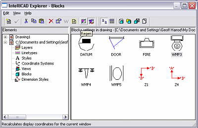
In paper space (TILEMODE=0), we can type MS to enter model space on a floating viewport, or use the space mode setting in the status bar and select this option from the Workspace dialog box. Choose Explore Layers from the Settings pull down menu to display the Drawing Explorer. The key thing to note here is that we have the ability to freeze layers in only the current viewport.
In the viewport containing the overall view, the layer DIMS5-1 is frozen only for the current viewport. Likewise, in the detail viewport, the layer DIMS1-5 is frozen. This means that the overall view displays the magenta dimensions and the detail view displays the red dimensions.

The end result is two viewports, each at different scale factors and showing different dimensions. In paper space the dimensions appear and will print at the same size because we have controlled overall scaling using dimension styles.
The basic rule is to determine which objects will be displayed selectively in different viewports and use separate layers for these objects.
Dimensions are a typical example of this requirement. It’s worth adopting a layer naming convention that allows you (and others) to readily discern these objects and also apply this naming convention to dimension styles. Where possible, you may want to use the same name for dimension styles and layers where visibility is associated.
 The main benefit of this approach is that the detail view is still a part of the main model. It’s not a copied object that we need to maintain and update separately. In our simple example, if the hole diameter or location changes, we will see this reflected immediately in the paper space views. We also have the benefit of associative dimensions that are placed in model space and update automatically alongside geometry changes.
With a little bit of forethought, this type of drawing structure is very easy to create and work with. Like most things in CAD, a little bit of extra work in setting things up correctly pays dividends when it comes to revising the design. With the 8 steps outlined in ‘Watch This Space‘ and these guidelines on layers and dimensions, I’m sure you’ll find many rewards in using the paper space environment.


