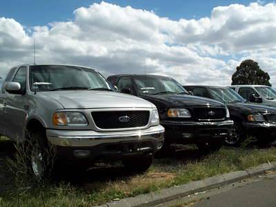
 XL Industries Pty Ltd was founded in the early 1990’s to manufacture vehicle service bodies, mainly for standard one-tonne cab chassis. For many years the business used a simple 2-D package for their drafting. But Nick Korganow (Managing Director) and Tony Frederiks (Design Coordinator) knew there must be a better way to improve the standard of the company’s design work.
They both felt the drafting packages they were using were not the ideal way to achieving good quality designs with the best efficiency. The guys looked to a engineering-oriented solid modeling package for an answer. They found SolidWorks to be the most capable and affordable product available. They have since added PhotoWorks to enhance the presentation of their designs.
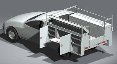
The XL Service Body is a one-piece, all steel unit with up to eight externally accessible, weather-tight side lockers, two lidded upper compartments and a central ‘utility’ section with tailgate.
XL Service Bodies are in use all over Australia, in New Zealand, Indonesia, Papua New Guinea and the Solomon Islands. XL’s customers range from small builders, plumbers, vets, pest controllers and service businesses to major national companies and local, state and federal government departments. Satisfied fleet users include Atlas Copco, Cummins Diesel, Hastings Deering, Isuzu-General Motors, Nissan Australia, NS Komatsu, Rolls Royce and Telstra.
Other XL Products include Field Service Bodies on chassis up to 5 tonnes, Hook Loaders, Lube Trucks and Toolboxes.
Case In Progress: The XL Hook Loader.
The XL Hook Loader is a hydraulic mechanism for loading and unloading a body on a one tonne utility. These machines are often seen on larger vehicles for loading bins.
 The design of the XL Hook Loader began with some geometry drawings sketched with a 2-D drawing package. The mechanism had a number of pivot points in which the positioning was critical. These points were to be contained within a framework which was to be kept as low as possible to ensure the vehicle tray body was kept to a usable height. The 2D drawings had been started but filed away in the “too hard basket” for some time because the trial and error process used to derive a usable frame geometry was taking too long.
At this stage the project was migrated into SolidWorks. The frame geometry was quickly sketched, and the parametric nature of the sketch editor allowed the geometry to be manipulated to give the ideal compromise between loading, unloading and tipping functions without requiring overly large hydraulic forces to actuate the machine. Once this geometry was settled there was enough information to warrant extra time and finances to be allocated to continue with the project until the prototype stage.
Over a period of three weeks a complete solid model was produced with multiple configurations showing the operation of the machine at various stages of its travel and a full set of workshop drawings were produced ready for the manufacture of the first prototype. Solidworks enabled that calculation of the mass properties of the machine so that the machine could be rated such that it would not overload the vehicle chassis and the first prototype could be tested with confidence. At this point in time pictures were produced for the initial promotional work.
 Over a period of one week the first prototype was built. The machining of bushes and small parts was performed by one person and the welding of the framework was done by one person. The hydraulics had been ordered prior to construction of the frame using the lengths calculated in SolidWorks. Once the hydraulics were installed and plumbed the machine was tested and worked exactly as expected first time.
A tray body was built for the utility and the first prototype was publicly displayed in Townsville at the North Queensland Government Field Day (May 17-18, 2000) where it generated substantial interest. The base model design has now also been adapted to suit a number of larger truck chassis with the design stages of the subsequent models has taken far less time than the first.
XL has found that SolidWorks does reduce the time required to get products to market over using traditional CAD as a design tool. It seems that by using SolidWorks it takes longer to produce the first set of workshop drawings but by that point in time there is much more than a set of workshop drawings produced.
 The mass properties are known, the alignment of mating parts has been checked, and the device has been viewed in three dimensional space so the designer knows whether it “looks right”. The above mentioned features take a lot of the guess work out of the initial design and enable more confidence in the fact that the first prototype will work.
Traditionally as many as four prototypes were built for one truck body before it could be deemed ready for production. The most recent “van type” service body which was developed using SolidWorks required only two prototypes and is one of the most complex bodies that has been designed so far. The initial “van type” service body was designed by traditional methods and was found not to be economically viable after the first batch produced.
Support has always been outstanding through the local SolidWorks distributor (Intercad) and the SolidWorks website. Generally it seems that every time we conceive an idea that would make SolidWorks a better package it is included in the next release. When problems are found they are usually corrected within the next service pack. Any instabilities that may have existed in the original version is improved upon with each new release.

